Sony CDX-L410X Installation Manual

Browse online or download Installation Manual for Car audio amplifiers Sony CDX-L410X. Sony CDX-L410X Installation Instructions User Manual

  • Download
  • Add to my manuals
  • Print
  • Page
    / 4
  • Table of contents
  • BOOKMARKS
  • Rated. / 5. Based on customer reviews
Page view 0
Sony Corporation © 2003 Printed in Korea
3-247-732-11 (1)
Cautions
This unit is designed for negative ground 12 V DC
operation only.
Do not get the wires under a screw, or caught in
moving parts (e.g. seat railing).
Before making connections, turn the car ignition
off to avoid short circuits.
Connect the yellow and red power input leads
only after all other leads have been connected.
Run all ground wires to a common ground
point.
Be sure to insulate any loose unconnected wires
with electrical tape for safety.
The use of optical instruments with this product
will increase eye hazard.
Notes on the power supply cord (yellow)
When connecting this unit in combination with
other stereo components, the connected car
circuit’s rating must be higher than the sum of
each component’s fuse.
When no car circuits are rated high enough,
connect the unit directly to the battery.
Parts Iist (1)
The numbers in the list are keyed to those in the
instructions.
The bracket 1 and the protection collar 3 are
attached to the unit before shipping. Before
mounting the unit, use the release keys 5 to
remove the bracket 1 and the protection collar 3
from the unit. For details, see “Removing the
protection collar and the bracket (4)” on the
reverse side of the sheet.
Keep the release keys 5 for future use as they
are also necessary if you remove the unit from
your car.
Caution
Handle the bracket 1 carefully to avoid injuring
your fingers.
Note
Before installing, make sure that the catches on both
sides of the bracket 1 are bent inwards 2 mm (
3
/32 in).
If the catches are straight or bent outwards, the unit will
not be installed securely and may spring out.
Installation/Connections
Installation/Connexions
FM/AM
Compact Disc
Player
Connection example (2)
Notes (2-B)
Be sure to connect the ground cord before
connecting the amplifier.
If you connect an optional power amplifier and do
not use the built-in amplifier, the beep sound will
be deactivated.
Connection diagram (3)
1 To a metal surface of the car
First connect the black ground lead, then connect
the yellow and red power input leads.
2 To the power antenna control lead or power
supply lead of antenna booster amplifier
Notes
It is not necessary to connect this lead if there is
no power antenna or antenna booster, or with
a manually-operated telescopic antenna.
When your car has a built-in FM/AM antenna in
the rear/side glass, see “Notes on the control
and power supply leads.”
3 To AMP REMOTE IN of an optional power
amplifier
This connection is only for amplifiers. Connecting
any other system may damage the unit.
4 To the +12 V power terminal which is
energized in the accessory position of the
ignition key switch
Notes
If there is no accessory position, connect to the
+12 V power (battery) terminal which is
energized at all times.
Be sure to connect the black ground lead to a
metal surface of the car first.
When your car has a built-in FM/AM antenna in
the rear/side glass, see “Notes on the control
and power supply leads.”
5 To the +12 V power terminal which is
energized at all times
Be sure to connect the black ground lead to a
metal surface of the car first.
2
A
B
AUDIO OUT REAR
1
45
Equipment used in illustrations (not supplied)
Appareils utilisés dans les illustrations (non fournis)
Rear speaker
Haut-parleur arrière
Front speaker
Haut-parleur avant
1
Power amplifier
Amplificateur de puissance
× 4
2
× 2
3
CDX-L410X
1
Catch
Page view 0
1 2 3 4

Summary of Contents

Page 1 - Compact Disc

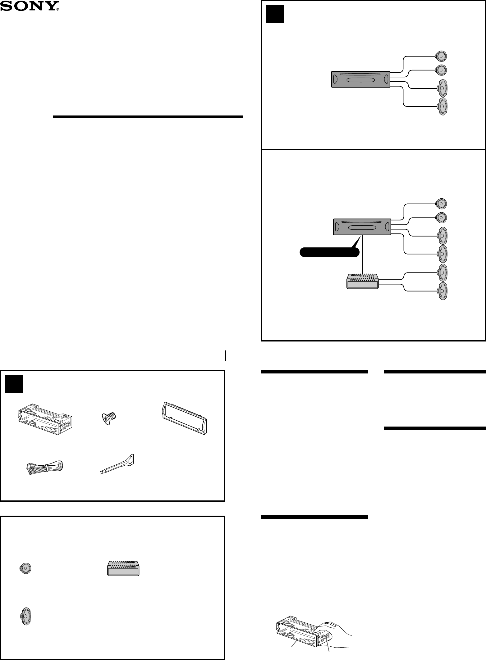
Sony Corporation © 2003 Printed in Korea3-247-732-11 (1)Cautions•This unit is designed for negative ground 12 V DCoperation only.•Do not get the wires

Page 2 - AUDIO OUT REAR

AUDIO OUTREARLRPrécautions•Cet appareil est exclusivement conçu pourfonctionner sur une tension de 12 V CC avec massenégative.•Évite de fixer des vis

Page 3

182 mm53 mm41 23311DashboardTableau de bord56 A TOYOTAto dashboard/center consoleau tableau de bord/console centraleBracketSupportBracketSupportB NISS

Page 4 - 2 Retirez le support 1

Precautions•Choose the installation location carefully sothat the unit will not interfere with normaldriving operations.•Avoid installing the unit in

Comments to this Manuals

No comments